Value in Red, Infrared

Article Courtesy of Steve Wright, Technical Services Representative
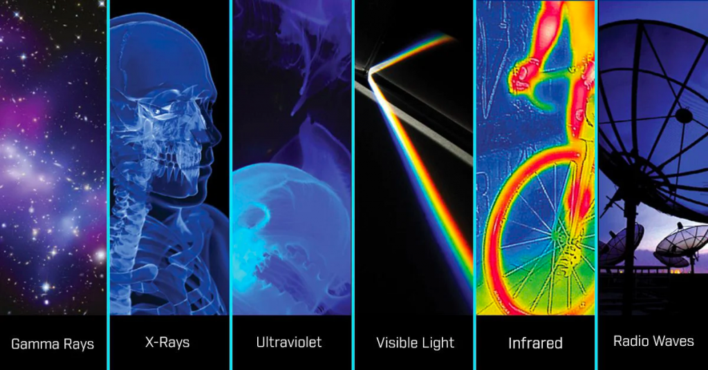
If we are to discuss infrared technology, we must discuss the electromagnetic spectrum (EMS.) The EMS describes for us the wavelengths over which there exist different forms of radiant energy. It may sound foreign or intimidating but you’re already familiar with it! So, with what part of the EMS are you familiar? Visible light for sure and likely x-rays, radio waves and you may recall hearing recently of ultraviolet light used to destroy viruses (see Figure 1.) There’s one more; if you just barely hover your hand over a hot stove, sun-exposed car hood, or other object that is hotter than you, what do you sense? Answer – infrared energy!
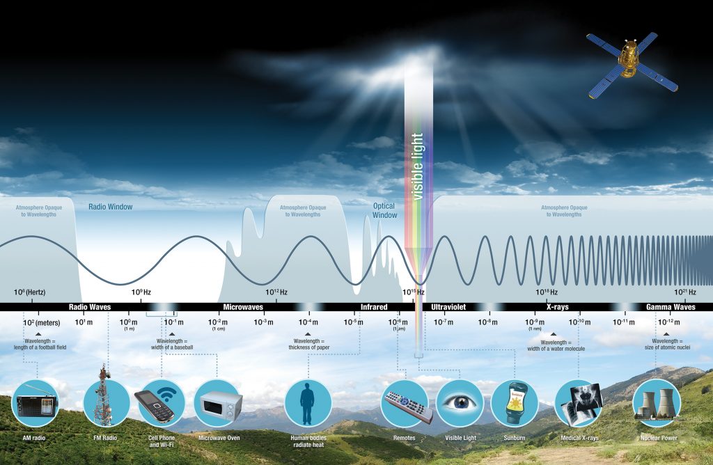
Looking at the EMS spectrum, wavelength scale, and Figure 2, you’ll notice that over the whole spectrum, there is only a very, very small range that includes visible light. We can’t see any of the rest of the EMS (note that the earth’s atmosphere blocks some of the EMS that occur naturally in space). Radio waves, infrared waves, ultraviolet waves, and x-rays are all invisible to our eyes; but we can use sensors to detect those invisible waves, that invisible energy. For example, a radio can be used as a sensor to detect radio waves. What are we doing when we do that? We’re using the radio to convert an invisible radio wave into an audible sound we can hear. GREAT NEWS – We can do similar with an infrared camera! The camera converts an infrared signal into a visual signal in the form of an image. This can be a very valuable tool for the electric utility industry because it then allows the visual depiction of heat!
Electric current flow through equipment, components, and connections will generate heat and therefore infrared radiation. If there is excess heat there may be a problem that then can be seen! If that problem can be found and corrected before damaging heat can result in a failure the utility can provide more reliable and cost-effective electric service to its consumers.
FLIR is the premier provider of infrared detecting cameras. If you’re a naturalist out looking for Bigfoot, you better have a FLIR infrared camera if you hope to find her/him. If you’re in law enforcement and looking for the bad guy/gal running through the woods at night, you better have a FLIR infrared camera. If you’re with an electric utility and you want to inspect the electric infrastructure serving the area hosting the Super Bowl, you better have a FLIR infrared camera.
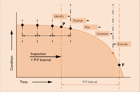
From the time a component is put into service, it is on its way to the end of life. Improper installation, extraordinary or unusual events, overloading, and other things can result in premature component failure. Of course, an unexpected failure can have negative and expensive consequences. Rather than operating under a run-to-failure mode, most system operators have an inspection program to assure components are operating within their design limits. This is to the benefit of the reliable service and cost-effective operation of the system. Figure 3 is a representative P-F curve; P is the point where impending component failure can be identified and F is where the component failure has occurred. A system owner’s goal will be to have enough time between the two points to identify, prioritize, plan, schedule, and execute the repair. It is very helpful to have an inspection tool that will show an impending problem as early as possible. This can allow for extended time intervals between inspections and better assure enough time between P & F to accommodate repair. By the time overheated electrical system connections are observable, it’s usually an emergency. An inspection tool and program that avoids an emergency is what’s needed. A tool that allows us to see the heating of components that represent pending failure. Infrared cameras are such a tool.
It’s great news that infrared cameras are a tool to help but how do we pick the right camera? Let’s start with questions about camera use that need to be asked, such as:
What level of training will the users have?
How easy must the camera be to use?
What quality of the viewable image on the visual screen is necessary?
For qualification or grading of fault (heat fault, not electrical fault) condition or severity, what quality of the infrared image is necessary?
Will the camera be in the hands of just one person or shared by a work team?
A very common question is, “How far can I see with the camera?”
The more appropriate question is at what distance and at what temperature difference do you want to see what size component?
The answers to these questions are necessary to select the most appropriate camera and possibly optional lenses.
IR cameras are just cameras, and everyone can use a camera. Does this mean anyone can accurately make decisions about thermal conditions using an IR camera? NO! Technology has improved dramatically over the last 20 years. The costs have come down and performance has gone up. Ease of use has also improved. However, an understanding of the technology and the camera are necessary for the user to make correct evaluations. It is easy to miscall an apparent component as HOT that is not hot or miss a hot component that is on the verge of failure. There are pitfalls and traps that can result in gross misinterpretation of an IR image. A wood pole can appear to be hot! Substation steel can easily appear to be HOT. Tip: if there’s an emergency call to replace a hot pole it’s time to ask some questions.
Although the technology has improved greatly, it still is behind that of visual cameras regarding image sharpness. An Apple iPhone 7 has a 12-megapixel camera. A Canon EOS Rebel T7 is a 24-megapixel camera. A well-featured low-end IR camera has a 160 x 120-pixel detector; that’s 0.019-megapixels. The highest-end handheld FLIR IR camera has a 1024x768 pixel detector; that’s 0.79 megapixels. You can see that in the world of IR, the image pixel count is not yet near that of visual cameras. Therefore, an IR image does not have the sharpness and detail of a visual camera image.
What is the best camera to purchase? Buy as many cameras as you can afford. The higher the pixel count the better. But, don’t acquire a camera that exceeds the capability of the user; and, keep in mind there are low-cost means to improve the capability of the user. Free training that is very suitable to personnel using lower-end ($1,000- $6,000), simple-to-use cameras, and fee certification training for seasoned users that will use more capable and complicated cameras ($10,000 - $35,000) are readily available.
How far can I see with the camera? Well, we broached the subject of pixels and we all know more is better. If one could magically hold the camera still and magically hold it such that one and only one pixel is “covered” by a hot object, let’s say 10 degrees Fahrenheit different from the surrounding, the hot object/pixel would likely be observable. Whether there’d be an accurate temperature measured or not is another question. It is recommended that to observe an accurate temperature difference there be nine pixels “covered” by the hot object, 3x3 pixels. Table 1 identifies a variety of cameras and lenses and the distances at which 1 and 3 pixels are covered by a 1” wide by approximately 1” tall object. I use these dimensions because that’s roughly the size of a connector of a cutout and the threaded cap of a fuse holder in a cutout. Let’s imagine there’s a 40 ft pole with a set of arm-mounted cutouts serving a capacitor bank. The cutouts might be mounted about 33 ft above ground. If you had a FLIR E8 you’d likely be able to “see” a hot cutout connection from near the base of the pole, but an accurate measurement would require that you get in a bucket and get to within 11 ft.
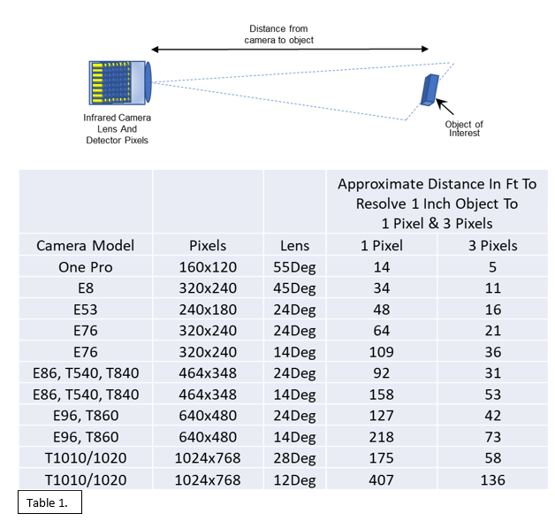
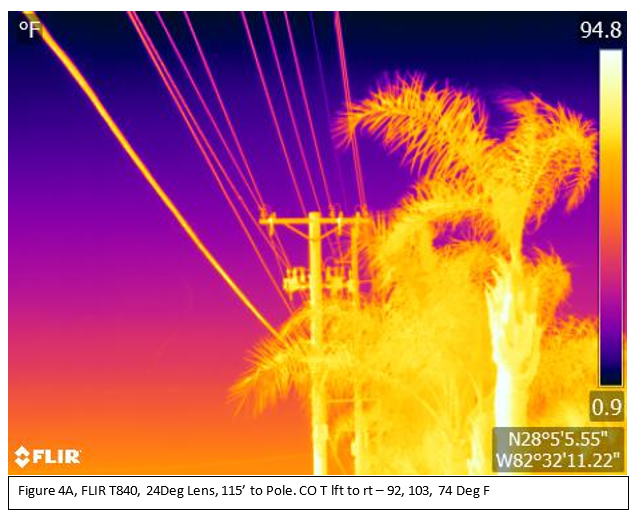
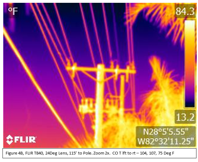
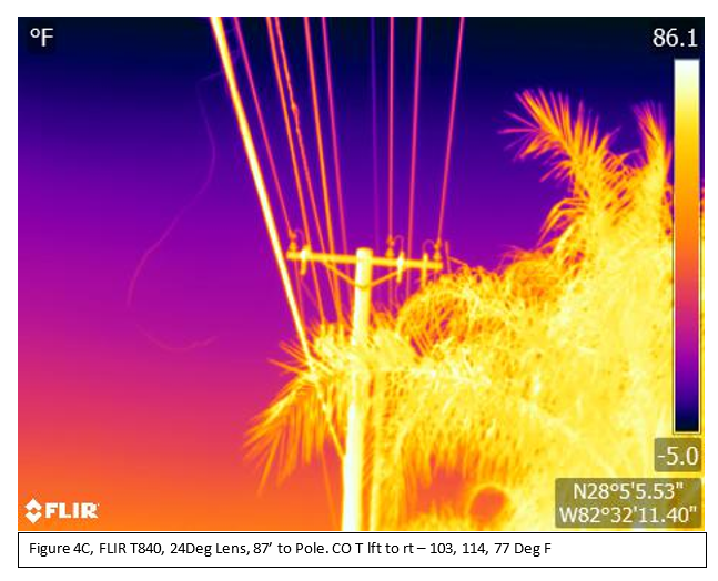
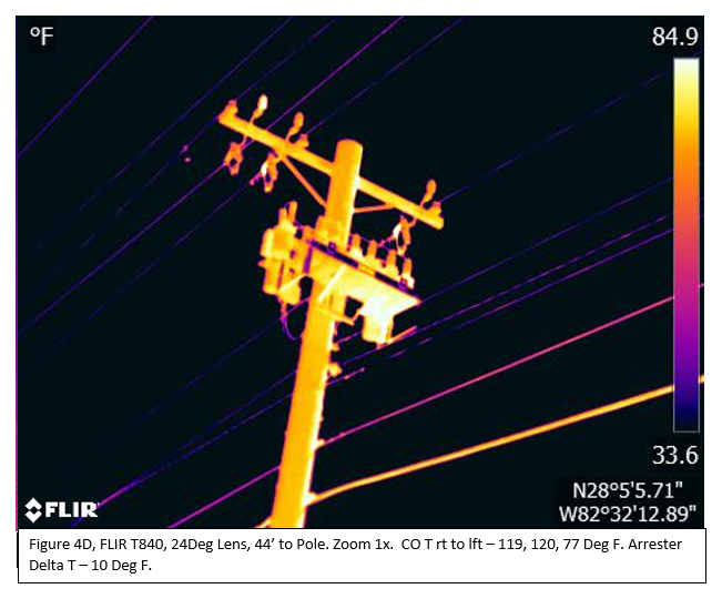
If you had a FLIR T840 with the standard 24-degree lens you might be able to “see” a hot cutout connector from about 90 ft; from near the base of the pole, you’d be able to get an accurate measurement. If you had a T860 with the 14-degree lens you’d be able to “see” the hot connector from about 216 ft and get a good temperature measurement at about 68 ft from the base of the pole. [Note these distances are not the tabulated distances because they are adjusted for height to the camera view screen assumed at 5 ft.] See Figures 4A – 4D for some images of a utility capacitor bank I acquired using a T840 with the standard 24 Deg lens. I saw what appeared to be several potential hot spots from over 100 ft. The cutout fuse holder top contact area was hot on two phases by about 50 Deg F. And there was an arrester that was about 10 Deg F hotter than the other two. Note the reflection of sunlight on the side of the palm tree. Reflection can result in erroneous calls of hot spots. View the suspect area from a different angle to verify whether or not the reflection is leading you down the wrong path. Be aware that when you observe a hot spot and you cannot get close enough to get an accurate temperature, no matter the camera and lens, you should expect the temperature to be hotter than observed.
I hope you see that IR cameras can be an incredibly useful tool that allows for the operation of a more reliable system. The inspections may be contracted or performed with utility personnel. Even if contracted it is extremely beneficial for the utility to have their own camera. There have been times when a contract thermographer accidentally called out the wrong phase in a report or made some other error; a post-inspection of corrective work by the utility can verify the right work was done and done correctly. Another valuable use is the pre-switching and post-switching inspection of substation equipment; the load changes may uncover previously unexposed issues. An IR camera is another tool for the toolbox; for about $2,500, one can easily and reliably check for unusual heating conditions before a hand is laid upon any equipment.
An IR camera is not just a camera. There are questions to be asked and answered in order that the best camera to be selected. Gresco can assist with those answers! Contact your technical representative today.
Sources:
Maximizing the P-F Interval Through Condition-Based Maintenance, Dale R. Blann, Principal/CEO
Marshall Institute Inc.
https://www.maintworld.com/Applications/Maximizing-the-P-F-Interval-Through-Condition-Based-Maintenance
The PF Interval – Is it Relevant in the world of Big Data?, Sandy Dunn, Assetivity
https://www.assetivity.com.au/article/reliability-improvement/the-pf-interval-is-it-relevant-in-the-world-of-big-data.html
What is Infrared?, https://www.flir.com/discover/what-is-infrared/
What’s The Difference between Thermal Imaging and Night Vision?, https://www.flir.com/discover/ots/thermal-vs-night-vision/
TOUR OF THE ELECTROMAGNETIC SPECTRUM, Ginger Butcher, Science Systems and Applications, Inc., for NASA, 3rd Edition: 2016. See also https://science.nasa.gov/ems/
Manage orders, payments, preferences and anything else about your account using our Customer Connect Portal.