Regulators and Distributed Generation
Article Courtesy of Brad Schafer, Sales Director, Technical Solutions
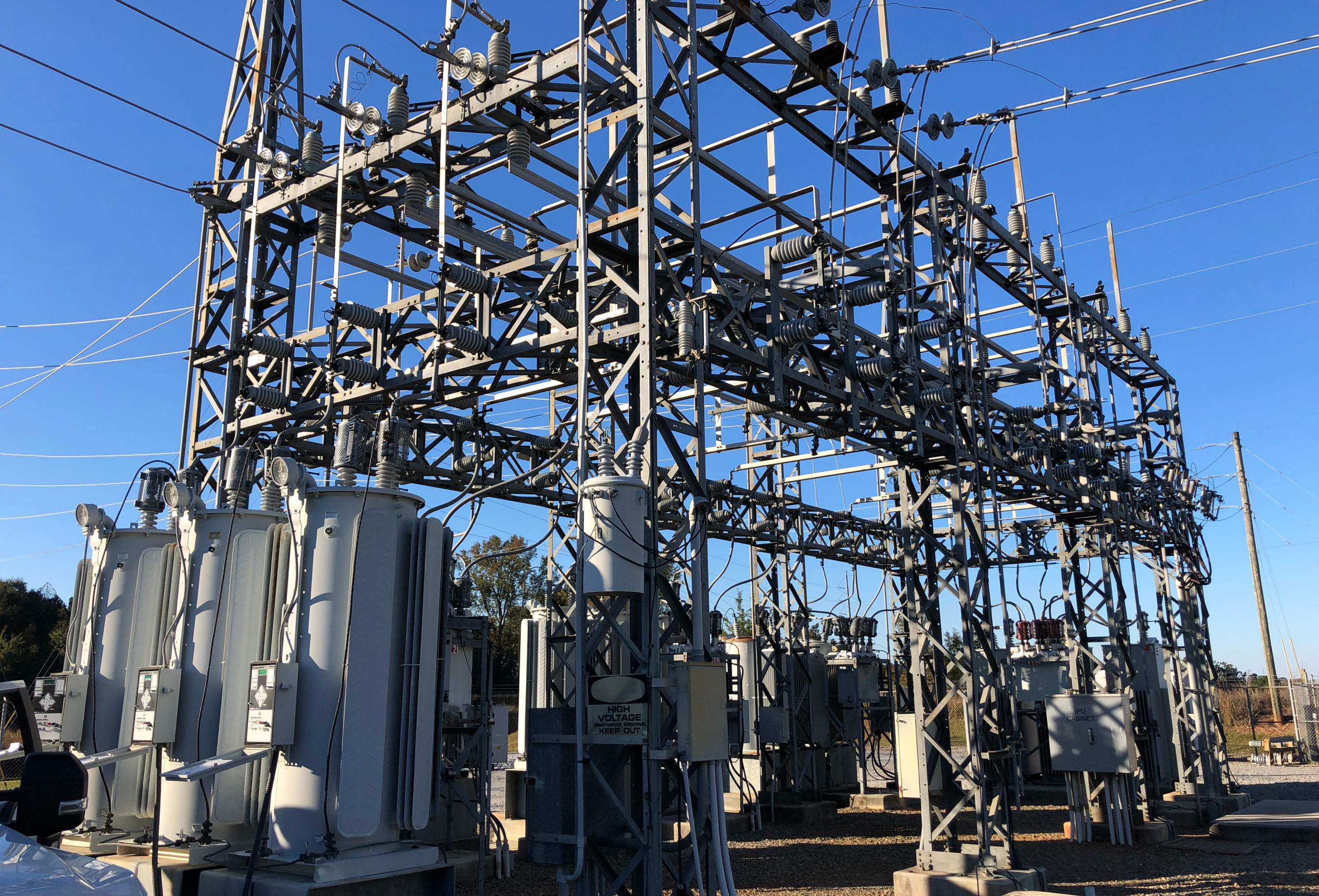
A utility company recently called us for technical support. They were recording high voltage on one of their circuits and the problem was intermittent. We narrowed down the likely suspects to the voltage regulators and decided to meet at the substation the next day.
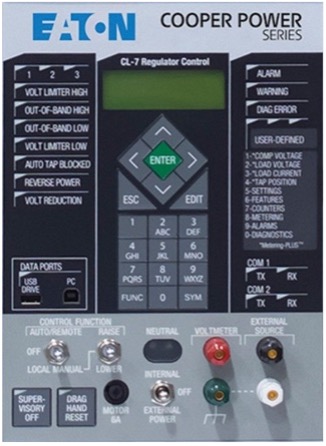
When we arrived in the morning, everything was working fine which only made diagnosing the issue more difficult. Thankfully, we didn’t have to wait long. After we had finished our visual inspection, the regulator AUTOTAP BLOCK light came on the front panel indicating the device was no longer regulating voltage.
.jpg)
Pressing hotkey #2 LOAD VOLTAGE, we could see the load voltage of the regulator was high. This matched the high downline voltages reported the day before. This reading could also be confirmed with a multimeter on the RED and WHITE terminals.
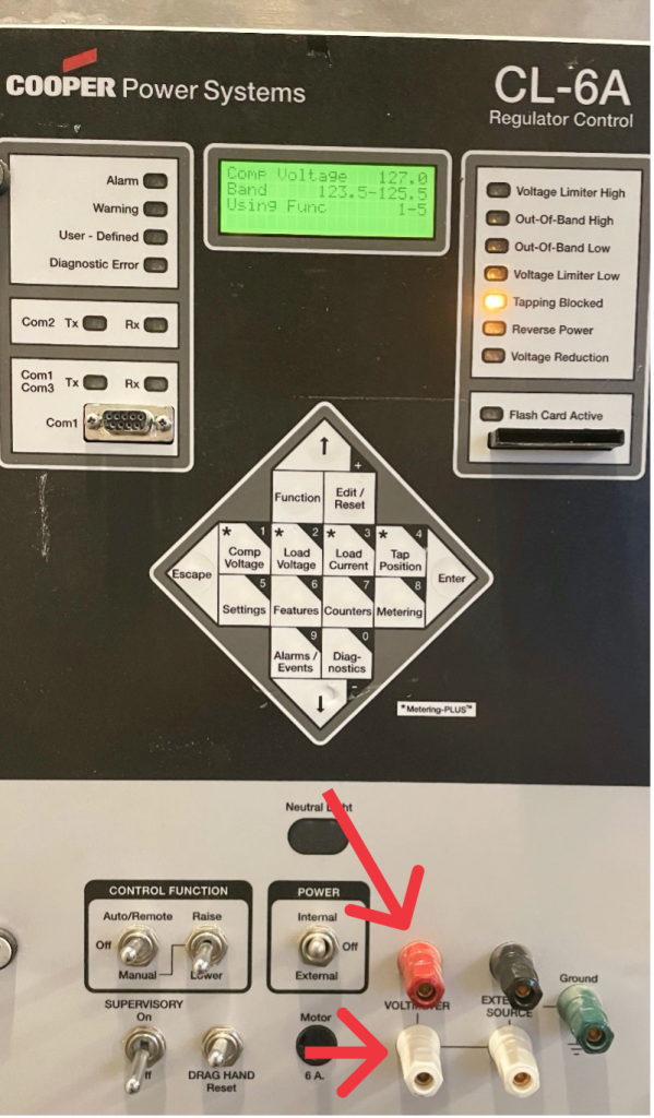
The second line of the LCD screen also shows the upper and lower regulation bands. For this application, the setpoint is 124.5 and the bandwidth is 2 volts, so the upper banding is 125.5 and the lower band is 123.5.
At this point, we know the panel is correctly measuring the output voltage. We also know the output voltage is higher than the accepted upper limit and the control should be trying to lower the tap position, but the control is not sending step-down commands. This is generally good news because it means the regulator is likely fine (no mechanical issues preventing the regulator from stepping) and we just need to understand why the control is not sending step-down commands to the regulator.
Our next step is to press hotkey #3 labeled LOAD CURRENT on the front panel. This hotkey will display a screen that shows the load current measured by the regulator, but more importantly, when the TAPPING BLOCKED led is lit, then the 4th line on the LCD screen will tell us why the regulator is not automatically adjusting the voltage.
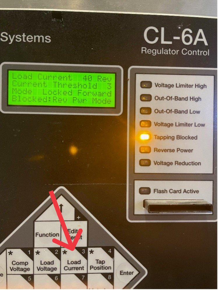
The fourth line reads, BLOCKED: REV PWR MODE. And this is confirmed in the first line where, to the right of the 40 amps, the letters REV indicates that the current flowing through the regulator is not coming from the source to the load, but from the load to the source.
Discussing the circuit design, there is a solar farm on this line and otherwise, the light circuit is lightly loaded. So, it is very likely that the solar farm output is large enough to power the circuit load and the excess power would flow through the regulator load side to the source side. As we were having this discussion, a few clouds come across the sky. The current decreases to zero and then begins to increase, but this time the power flow is forward. The TAPPING BLOCKED led turns off and the voltage regulator begins tapping down to correct the load-side voltage. We watched that transition happen several times through the course of the day. It was surprising how quickly the power output of the solar farm would change with small variations in cloud cover.
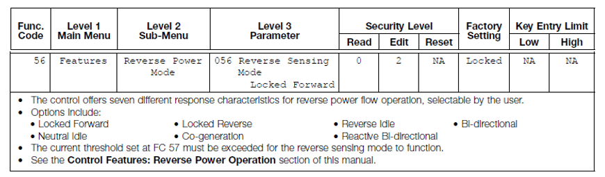
We needed to make some adjustments to the settings since these regulators could experience reverse power flow on a regulator basis. Function Code 56 specifies how the control should respond to reverse power.
CL6 – Reverse Sensing Modes
This control was set up for the default function: LOCKED FORWARD. In this mode, if the control measures reverse power flow, then the regulator will IDLE and wait for forward power flow to resume.
For this scenario, we will use the Co-Generation mode. With Co-Generation mode, the regulator recognizes that reverse power flow may happen, but the source of that reverse power flow is another generation source and in that scenario, the regulator should continue to regulate the load-side voltage. The solar farm on the load side is designed to match the voltage of the line and inject energy into the system. In Co-Generation mode, the regulator maintains the load-side voltage within the correct band keeping all the customers and the solar farm within the desired voltage parameters.
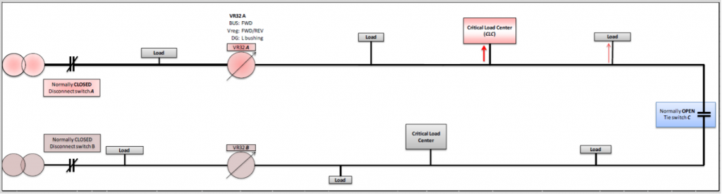
Regulators can also experience reverse power flow when we use them downline and use TIE SWITCHES to back feed circuits. In the diagram below, we have two circuits from two substations and both circuits have a downline regulator. If we were to lose transmission to one of the substations, then all the customers on that circuit would lose power. But if we open the recloser/breaker inside the substation and close the normally open TIE SWITCH, then we can back feed that circuit and keep power to the customers while we wait for transmission power to be restored. The regulator on the back-fed circuit will experience reverse power flow. Unlike the solar farm scenario, the stiff voltage source will now be on the regulator's load side and the regulator will need to regulate the source side voltage. In this scenario, we would use the Bi-Directional Reverse Power Mode.
With the combination of the CL7 control and Eaton Quik Drive Tap Changer, we also gain an improved version of the Bi-Directional mode called the Bias Bi-Directional mode. At low currents, it can be difficult for a regulator control to measure if the power flow is forward or reverse. When in a low current state, the Bias Bi-Directional mode has the regulator take two quick steps to measure where the voltage changes, on the load or source side. With that information, the regulator knows which direction to regulate the voltage, and the control doesn’t have to idle waiting for the current to increase
.png)
CL7 – Reverse Sensing Modes
Regulators and distributed generation can become even more complicated with the combination of distributed generation and back feeding with a TIE SWITCH. With the combination of the CL7 control and the Quik Drive Tap Changer, we have the new option of using Bias Co-Generation mode. This mode can differentiate between reverse power flow due to back feeds and reverse power flow due to Generation. Like the Bias Bi-Directional mode, two quick steps are used to determine if the reverse power flow is due to generation or the TIE SWITCH being closed.
.png)
Distributed generation is a growing trend in our industry, and we continue to adapt to new challenges. If you need more information for your regulator application, please contact your Gresco Sales Engineer.
Manage orders, payments, preferences and anything else about your account using our Customer Connect Portal.