Anatomy of a Lighting Plan
The support Gresco provides in Lighting Design is well-known, but how we request and utilize this data is not.
We can assist with lighting recommendations for most lighting applications including subdivisions, general roadway lighting, DOT roadway calculations, Intersections, RoundAbouts, and High Mast applications.
We also provide recommendations for schools, churches, medical facilities, municipal complexes, retail and commercial sites, parks and recreation, and industrial or distribution facility sites. Solutions include decorative or pedestrian-scale lighting and large-area lighting options.
Lighting recommendations for control rooms, warehouse lighting, parking deck, or event space are options if they are for a Public Power’s property.
The information required for a lighting plan includes a scale drawing in pdf or DWG format. We need to know the lighting objectives for the project and any lighting ordinances or standards that need to be considered. We also take fixture standards into consideration. If there are any special parameters or products, information on those needs to be provided as well.
Let’s look at the anatomy of a plan and determine what information is available and how to utilize it.
Fixture Schedule
.png)
The symbol in conjunction with the arrangement in the table provides visual and verbal details on the quantity and orientation of lights on a pole. In this example, the first symbol indicated there are two lights on a single pole, 1800 apart. The second symbol is a single fixture per pole.
The quantity is the total number of a specific arrangement in the design. If you were looking at a quote for this you would have a total of 161 Navion, 4 cube, T4W, and 4000K fixtures.
The label and description do not show options like color, mounting option specifics like bolt-on arms versus mast arm mounting, surge protection, warranty, and so on. The description is alike for both fixtures confirming both lines are the same fixture. The label is different to allow for the configuration using just the _1 to indicate there is a difference in the usage.
The LLF is Light Loss Factor. This metric is used to provide maintained lumen levels based on manufacturer’s reports. Illuminating Engineering Recommendations provide for lighting criteria at a future point rather than initial lighting performance. In this example, the light will lose less than 10% of the initial lumens, and from the manufacturer’s literature based on 60,000 hours in the future. It also takes into consideration the effect of dirt on performance.
Luminaire Location Summary
.png)
The plan may also label the number next to the locations on the site plan for coordination if this option is selected by the designer. We often use Luminaire Numbers and Labels at each symbol location on the drawing.
The label is the specific light used at the location identified in the lighting schedule.
The X and Y are drawing coordinates based on the drawing origin as measurable distances for setting the poles.
Z is the same as the mounting height or lamp center for tall decorative pedestrian lights.
Orientation is the directional rotation of the optics.
Tilt is the number of degrees from Nadir (straight down) that the fixture is tilted for flood lighting. Fixed arm type fixtures will be 0 tilt as you cannot tilt them.
Calculation Summary
.png)
The label identifies the specific area of calculation. Designs may break areas into specific lots, roadways, or other areas of interest.
Calculation Type identifies the type of calculations performed. Illuminance is lighting that strikes the surface of the site while roadway lighting is based on luminance which is the amount of light that is reflected off the surface of the site.
Units if the metric of measure; footcandles for illuminance and candela/sq ft for luminance.
Average is a metric that identifies how much light is based on the average of all the measurements taken in the model. Most standards specify an average metric however site lighting looks at minimum footcandle as a guiding parameter.
Max is the highest reading across the plan. Some ordinances provide maximum limits
Minimum is the lowest reading across the plan and is used in site lighting parameters.
Avg to Min and Max to Min are uniformity ratios. They assist the designer in making sure the lighting does not exceed bright-to-dark limits that can cause visual fatigue to the viewer. Roadway lighting has specific uniformity ratios.
There are other parameters that can be added for sports lighting and roadway lighting, such as Coefficient of Variance and Veiling Luminance used in specific applications.
Plan
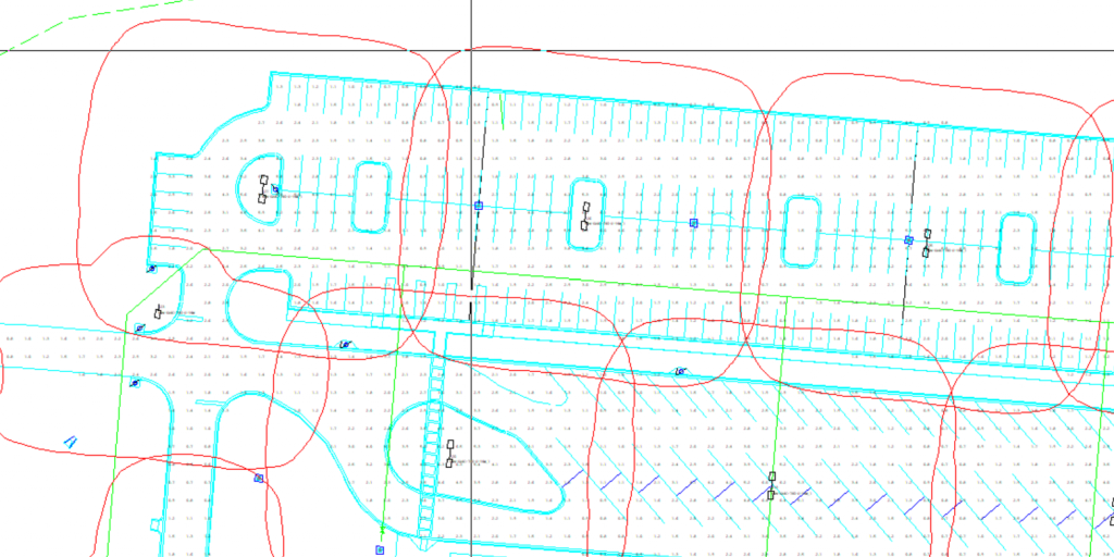
This snip of the plan shows the following elements:
The gray numbers are the footcandle readings at specified intervals that are to scale in the drawing. These are maintained levels at that specific point.
The red lines around the fixture symbol show the light pattern at specified limits. A designer that wanted to have a 0.50 fc minimum on this site would use a 0.25 fc iso-line to determine how far you could space fixtures with the lines touching to maintain the desired minimum.
There are labels at each fixture location showing the number correlation to the fixture location schedule and the fixture label. This snapshot shows twins and singles in the design.
Gresco appreciates the opportunity to assist with your lighting needs and we hope this tutorial is helpful should you need a design or in understanding the elements that are provided in the plan. Let your account manager know if we can assist in any way!
Manage orders, payments, preferences and anything else about your account using our Customer Connect Portal.